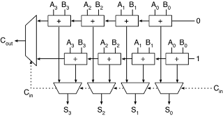
A carry select adder is a special way of implementing a binary adder. Its simple yet fast adder. The block diagram below shows how you can implement a carry select adder.
module fulladder
( input a,b,cin,
output sum,carry
);
assign sum = a ^ b ^ cin;
assign carry = (a & b) | (cin & b) | (a & cin);
endmodule

The '+' blocks are full adders and mux's used are 2:1 size.
The Verilog codes are given below:
fulladder.v
module fulladder
( input a,b,cin,
output sum,carry
);
assign sum = a ^ b ^ cin;
assign carry = (a & b) | (cin & b) | (a & cin);
endmodule
multiplexer2.v
module multiplexer2
( input i0,i1,sel,
output reg bitout
);
always@(i0,i1,sel)
begin
if(sel == 0)
bitout = i0;
else
bitout = i1;
end
endmodule
( input i0,i1,sel,
output reg bitout
);
always@(i0,i1,sel)
begin
if(sel == 0)
bitout = i0;
else
bitout = i1;
end
endmodule
carry_select_adder.v
module carry_select_adder
( input [3:0] A,B,
input cin,
output [3:0] S,
output cout
);
wire [3:0] temp0,temp1,carry0,carry1;
//for carry 0
fulladder fa00(A[0],B[0],1'b0,temp0[0],carry0[0]);
fulladder fa01(A[1],B[1],carry0[0],temp0[1],carry0[1]);
fulladder fa02(A[2],B[2],carry0[1],temp0[2],carry0[2]);
fulladder fa03(A[3],B[3],carry0[2],temp0[3],carry0[3]);
//for carry 1
fulladder fa10(A[0],B[0],1'b1,temp1[0],carry1[0]);
fulladder fa11(A[1],B[1],carry1[0],temp1[1],carry1[1]);
fulladder fa12(A[2],B[2],carry1[1],temp1[2],carry1[2]);
fulladder fa13(A[3],B[3],carry1[2],temp1[3],carry1[3]);
//mux for carry
multiplexer2 mux_carry(carry0[3],carry1[3],cin,cout);
//mux's for sum
multiplexer2 mux_sum0(temp0[0],temp1[0],cin,S[0]);
multiplexer2 mux_sum1(temp0[1],temp1[1],cin,S[1]);
multiplexer2 mux_sum2(temp0[2],temp1[2],cin,S[2]);
multiplexer2 mux_sum3(temp0[3],temp1[3],cin,S[3]);
endmodule
tb_adder.v (testbench code)
module tb_adder;
// Inputs
reg [3:0] A;
reg [3:0] B;
reg cin;
// Outputs
wire [3:0] S;
wire cout;
integer i,j,error;
// Instantiate the Unit Under Test (UUT)
carry_select_adder uut (
.A(A),
.B(B),
.cin(cin),
.S(S),
.cout(cout)
);
//Stimulus block - all the input combinations are tested here.
//the number of errors are recorded in the signal named "error".
initial begin
// Initialize Inputs
A = 0;
B = 0;
error = 0;
//for carry in =0
cin = 0;
for(i=0;i<16;i=i+1) begin
for(j=0;j<16;j=j+1) begin
A = i;
B = j;
#10;
if({cout,S} != (i+j))
error <= error + 1;
end
end
//for carry in =1
cin = 1;
for(i=0;i<16;i=i+1) begin
for(j=0;j<16;j=j+1) begin
A = i;
B = j;
#10;
if({cout,S} != (i+j+1))
error <= error + 1;
end
end
end
endmodule
Waveform after functional simulation:
The code was synthesised and simulated using Xilinx ISE 14.6. The waveform is too long to show on a single screenshot. So I have selected a relevant section to show here.
S0,s1,s2,s3 what are thease
ReplyDeleteselect lines
DeleteSums of each adder
ReplyDeleteoutput showed here is different code makes different output pls
ReplyDelete