Long back I had posted a simple matrix multiplier which works well in simulation but couldn't be synthesized. But many people had requested for a synthesizable version of this code. So here we go.
The design takes two matrices of 3 by 3 and outputs a matrix of 3 by 3. Each element is stored as 8 bits. This is not a generic multiplier, but if you understand the code well, you can easily extend it for different sized matrices.
Each matrix has 9 elements, each of which is 8 bits in size. So I am passing the matrix as a 72 bit 1-Dimensional array in the design. The following table shows how the 2-D elements are mapped into the 1-D array.
Row | Column | Bit’s Position in 1-D array |
0 | 0 | 7:0 |
0 | 1 | 15:8 |
0 | 2 | 23:16 |
1 | 0 | 31:24 |
1 | 1 | 39:32 |
1 | 2 | 47:40 |
2 | 0 | 55:48 |
2 | 1 | 63:56 |
2 | 2 | 71:64 |
Let me share the codes now...
matrix_mult.v:
//3 by 3 matrix multiplier. Each element of the matrix is 8 bit wide.
//Inputs are named A and B and output is named as C.
//Each matrix has 9 elements each of which is 8 bit wide. So the inputs is 9*8=72 bit long.
module matrix_mult
( input Clock,
input reset, //active high reset
input Enable, //This should be High throughout the matrix multiplication process.
input [71:0] A,
input [71:0] B,
output reg [71:0] C,
output reg done //A High indicates that multiplication is done and result is availble at C.
);
//temperory registers.
reg signed [7:0] matA [2:0][2:0];
reg signed [7:0] matB [2:0][2:0];
reg signed [7:0] matC [2:0][2:0];
integer i,j,k; //loop indices
reg first_cycle; //indicates its the first clock cycle after Enable went High.
reg end_of_mult; //indicates multiplication has ended.
reg signed [15:0] temp; //a temeporary register to hold the product of two elements.
//Matrix multiplication.
always @(posedge Clock or posedge reset)
begin
if(reset == 1) begin //Active high reset
i = 0;
j = 0;
k = 0;
temp = 0;
first_cycle = 1;
end_of_mult = 0;
done = 0;
//Initialize all the matrix register elements to zero.
for(i=0;i<=2;i=i+1) begin
for(j=0;j<=2;j=j+1) begin
matA[i][j] = 8'd0;
matB[i][j] = 8'd0;
matC[i][j] = 8'd0;
end
end
end
else begin //for the positve edge of Clock.
if(Enable == 1) //Any action happens only when Enable is High.
if(first_cycle == 1) begin //the very first cycle after Enable is high.
//the matrices which are in a 1-D array are converted to 2-D matrices first.
for(i=0;i<=2;i=i+1) begin
for(j=0;j<=2;j=j+1) begin
matA[i][j] = A[(i*3+j)*8+:8];
matB[i][j] = B[(i*3+j)*8+:8];
matC[i][j] = 8'd0;
end
end
//re-initalize registers before the start of multiplication.
first_cycle = 0;
end_of_mult = 0;
temp = 0;
i = 0;
j = 0;
k = 0;
end
else if(end_of_mult == 0) begin //multiplication hasnt ended. Keep multiplying.
//Actual matrix multiplication starts from now on.
temp = matA[i][k]*matB[k][j];
matC[i][j] = matC[i][j] + temp[7:0]; //Lower half of the product is accumulatively added to form the result.
if(k == 2) begin
k = 0;
if(j == 2) begin
j = 0;
if (i == 2) begin
i = 0;
end_of_mult = 1;
end
else
i = i + 1;
end
else
j = j+1;
end
else
k = k+1;
end
else if(end_of_mult == 1) begin //End of multiplication has reached
//convert 3 by 3 matrix into a 1-D matrix.
for(i=0;i<=2;i=i+1) begin //run through the rows
for(j=0;j<=2;j=j+1) begin //run through the columns
C[(i*3+j)*8+:8] = matC[i][j];
end
end
done = 1; //Set this output High, to say that C has the final result.
end
end
end
endmodule
tb_matrix_mult.v:
//Testbench for testing the 3 by 3 matrix multiplier.
module tb_matrix_mult; //testbench module is always empty. No input or output ports.
reg [71:0] A;
reg [71:0] B;
wire [71:0] C;
reg Clock,reset, Enable;
wire done;
reg [7:0] matC [2:0][2:0];
integer i,j;
parameter Clock_period = 10; //Change clock period here.
initial
begin
Clock = 1;
reset = 1;
#100; //Apply reset for 100 ns before applying inputs.
reset = 0;
#Clock_period;
//input matrices are set and Enable input is set High
A = {8'd9,8'd8,8'd7,8'd6,8'd5,8'd4,8'd3,8'd2,8'd1};
B = {8'd1,8'd9,8'd8,8'd7,8'd6,8'd5,8'd4,8'd3,8'd2};
Enable = 1;
wait(done); //wait until 'done' output goes High.
//The result C should be (93,150,126,57,96,81,21,42,36)
#(Clock_period/2); //wait for half a clock cycle.
//convert the 1-D matrix into 2-D format to easily verify the results.
for(i=0;i<=2;i=i+1) begin
for(j=0;j<=2;j=j+1) begin
matC[i][j] = C[(i*3+j)*8+:8];
end
end
#Clock_period; //wait for one clock cycle.
Enable = 0; //reset Enable.
#Clock_period;
$stop; //Stop the simulation, as we have finished testing the design.
end
//generate a 50Mhz clock for testing the design.
always #(Clock_period/2) Clock <= ~Clock;
//Instantiate the matrix multiplier
matrix_mult matrix_multiplier
(.Clock(Clock),
.reset(reset),
.Enable(Enable),
.A(A),
.B(B),
.C(C),
.done(done));
endmodule //End of testbench.
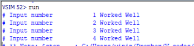
Simulation Results:
The design was simulated successfully using Modelsim SE 10.4a version. Screenshot of the simulation waveform is shown below:
Please let me know if you are unable to get the code to work or if its not synthesisable. Good luck with your projects.