A polynomial equation is an equation which is formed with variables, coefficients and exponents. They can be written in the following format:
y =anxn + an-1xn-1 + ... +a1x + a0 .
Here an, an-1 ... , a1 ,a0 are coefficients,
n, n-1, ... etc are exponents and x is the variable.
In this post, I want to share, Verilog code for computing the value of 'y' if you know the value of 'x' and coefficients forming the polynomial.
Directly calculating the polynomial with the above equation is very inefficient. So, first we reformat the equation as per Horner's rule:
y =(((anx + an-1)x + an-2)x + an-3)x + ... )x +a0 .
This modified equation can be represented by the following block diagram:
There are 3 sub-modules in the above block diagram.
1) Block number 1:
This block keep generating successive powers of input x.
In the first clock cycle it generates x^0 = 1.
In the 2ndclock cycle it generates x^1.
In the 3rd clock cycle it generates x^2.
In the nth clock cycle it generates x^(n-1).
Every clock cycle, the previous outputs are multiplied with 'x' to get the next power of x.
2)Block number 2:
The powers of x generated in the first block are multiplied with the corresponding coefficients of the polynomial in Block numbered 2. The coefficients are declared and initialized in the top level entity and can be changed easily.
3)Block number 4:
This block is basically an accumulative adder which accumulates all the products generated by the multiplier. Once it does 'n' additions, we have the final result available in output 'y'. An output 'done' is set as high to indicate that the output is ready.
Let me share the Verilog codes for these modules along with the testbench.
1) power_module.v
//This module generates successive powers of input x in each clock cycle.
//For example 1,x,x^2,x^3,x^4 etc.
//The output from the previous cycle is multiplied again by x to get the next power.
//The output from this entity is passed to the multiplier module, where it gets
//multiplied by the corresponding coefficient.
module power_module
#(parameter N = 32)
( input Clock,
input reset,
input signed [N-1:0] x,
output signed [N-1:0] x_powered
);
reg signed [N-1:0] x_pow;
reg signed [2*N-1:0] temp_prod;
always @(posedge Clock or posedge reset )
begin
if(reset == 1) //asynchronous active high reset.
x_pow = 1;
else begin
temp_prod = x*x_pow;
//The MSB half of the result is ignored. We assume that all intermediate powers of x
//can be represented by a max of N bits.
x_pow = temp_prod[N-1:0];
end
end
assign x_powered = x_pow;
endmodule
2) multiplier.v
//The successive powers of x are multiplied by the corresponding coeffcients here.
//The results are sent to the adder module which acts as an "accumulator".
module multiplier
#(parameter N = 32)
( input Clock,
input signed [N-1:0] x,y,
output reg signed [N-1:0] prod
);
reg signed [2*N-1:0] temp_prod;
always @(posedge Clock) begin
if(Clock == 1) begin
temp_prod = x*y;
//The MSB half of the result is ignored. We assume that all intermediate numbers
//are represented by a max of N bits.
prod = temp_prod[N-1:0];
end
end
endmodule
3) adder.v
//The output from multiplier module is received by this module and accumulated to
//form the output. If the polynomial equation has a degree of 'n' then 'n' additions has to take place
//to get the final result.
module adder
#(parameter N = 32)
( input Clock,reset,
input signed [N-1:0] x,
output signed [N-1:0] sum
);
reg signed [N-1:0] temp_sum;
always @(posedge Clock or posedge reset )
begin
if(reset == 1) //asynchronous active high reset.
temp_sum = 0;
else begin
temp_sum = temp_sum + x;
end
end
assign sum = temp_sum;
endmodule
4) Top Level Entity : poly_eq_calc.v
//This is the top level module for the polynomial equation calculator.
//The power_module, multiplier and adder modules are instantiated inside this top level block.
//When the output signal done is High, the output available at the 'y' output is the result we want.
//Ignore all other values of 'y' when done is Low.
//We have assumed that all the intermediate numbers calculated to reach the final result, can be represented
//by a maximum of N bits. This simplifies the design very much.
module poly_eq_calc
#(parameter N = 32)
( input Clock,
input reset,
input signed [N-1:0] x,
output signed [N-1:0] y,
output reg done
);
wire signed [N-1:0] x_powered,product_from_mult;
reg signed [N-1:0] coeff;
reg reset_adder;
integer coeff_index;
parameter NUM_COEFFS = 4; //Change here to change the degree of the polynomial.
reg signed [N-1:0] Coeffs [0:NUM_COEFFS-1];
//Eq : 3*x^3 - 2*x^2 - 4*x + 5;
//The coefficients belonging to higher powers of x are stored in higher addresses in Coeffs array.
initial begin
Coeffs[0] = 5;
Coeffs[1] = -4;
Coeffs[2] = -2;
Coeffs[3] = 3;
end
//Instantiate the 3 sub-modules.
power_module #(.N(N)) calc_power_of_x
(Clock,reset,x,x_powered);
multiplier #(.N(N)) multiply
(Clock,x_powered,coeff,product_from_mult);
adder #(.N(N)) add
(Clock,reset_adder,product_from_mult,y);
//The Always block controlling the 3 sub-modules and also supplying them with coefficients.
always @(posedge Clock or posedge reset )
begin
if(reset == 1) begin //asynchronous active high reset.
done = 0;
coeff_index = 0;
coeff = Coeffs[0];
reset_adder = 1;
end
else begin
//the disabling of 'reset of adder' gets noticed by adder entity in the next clock cycle.
reset_adder = 0;
if(coeff_index < NUM_COEFFS-1) begin
coeff_index = coeff_index+1;
coeff = Coeffs[coeff_index]; //send the coefficients one by one to the multiplier module.
end
else if(coeff_index == NUM_COEFFS-1)
coeff_index = coeff_index+1;
else
done = 1; //The final result is available in 'y' now.
end
end
endmodule
5) Testbench : tb_poly_eq_calc.v
//Testbench code.
module tb_poly_eq_calc; //testbench module is always empty. No input or output ports.
parameter Clock_period = 10; //Change clock period here.
parameter N = 32; //change the width of input and output here.
reg Clock;
reg reset;
reg [N-1:0] x;
wire [N-1:0] y;
wire done;
integer input_num;
//Apply inputs here. Only 'x' can be changed here.
//To change coefficients and degree of polynomial edit the top level module directly.
initial
begin
Clock = 0;
input_num = 0;
reset = 1;
#(Clock_period * 2.5);
reset = 0;
apply_input(4); //first input.
apply_input(7); //second input.
apply_input(15); //third input.
apply_input(-9); //fourth input.
#Clock_period; //wait for one clock cycle.
$stop; //Stop the simulation, as we have finished testing the design.
end
//the verilog task for applying one input.
task apply_input;
input [N-1:0] x_in;
begin
reset = 1;
#Clock_period;
reset = 0;
x = x_in;
#Clock_period;
wait(done); //wait for result to be out.
check_result(x_in); //verify the result.
#Clock_period;
end
endtask
//Verilog task to check if the results are correct and report.
task check_result;
input [N-1:0] x_in;
integer actual_res;
begin
wait(Clock);
if(done == 1) begin
//Change this equation if you change the polynomial eq inside the top level module.
actual_res = 3*x_in*x_in*x_in - 2*x_in*x_in - 4*x_in + 5;
input_num = input_num+1;
if(actual_res == y)
$display("Input number %d Worked Well",input_num);
else
$display("Input number %d Has Error",input_num);
end
end
endtask
//generate a 50Mhz clock for testing the design.
always #(Clock_period/2) Clock <= ~Clock;
//Instantiate the polynomial calculator.
poly_eq_calc #(.N(N)) poly_calculator
(.Clock(Clock),
.reset(reset),
.x(x),
.y(y),
.done(done));
endmodule //End of testbench.
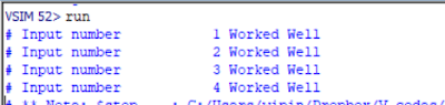
The code was simulated successfully using Modelsim 10.4a version. The simulation waveform below shows the signals for the first set of input:


//The MSB half of the result is ignored. We assume that all intermediate numbers
ReplyDelete//are represented by a max of N bits.
I didn't understand this statement. Can you elaborate this?
Thank You
if x is 4 bit x*x should be 8 bit ideally. and x^3 should be 12 bit and so on. But we assume that x is small enough that x^n will be still 4 bit. thats all.
Delete