In a previous article I posted the Verilog code for 2:1 MUX using behavioral level coding. In this post I have shared the code for the same 2:1 MUX with a gate level approach.
A 2:1 MUX is simple combinational circuit which follows the following Inputs-Output relationship:
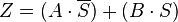
Where,
Z is the output.
A and B are data inputs.
S is the select signal.
To create the circuit, I have used built in primitive logic gates in Verilog. The gates have one output and multiple inputs. The first signal is the output and the remaining ones are inputs.
2:1 MUX with Gate level modelling:
//declare the Verilog module - The inputs and output signals.
module mux2to1(
Data_in_0,
Data_in_1,
sel,
Data_out
);
//what are the input ports.
input Data_in_0;
input Data_in_1;
input sel;
//What are the output ports.
output Data_out;
//Internal variables.
wire not_sel;
wire temp1,temp2;
wire Data_out_temp;
//NOT gate - first signal(not_sel) is output and others are inputs.
not n1(not_sel,sel);
//AND gate - first signal(temp1 and temp2) is output and others are inputs.
and and_1(temp1,Data_in_0,not_sel);
and and_2(temp2,Data_in_1,sel);
//OR gate - first signal(Data_out_temp) is output and others are inputs.
or or_1(Data_out_temp,temp1,temp2);
//Assign the final value to the output port.
assign Data_out = Data_out_temp;
endmodule
To simulate this code you can use the same testbench code available in this post. The simulated waveform is also available here.
A 2:1 MUX is simple combinational circuit which follows the following Inputs-Output relationship:
Where,
Z is the output.
A and B are data inputs.
S is the select signal.
To create the circuit, I have used built in primitive logic gates in Verilog. The gates have one output and multiple inputs. The first signal is the output and the remaining ones are inputs.
2:1 MUX with Gate level modelling:
//declare the Verilog module - The inputs and output signals.
module mux2to1(
Data_in_0,
Data_in_1,
sel,
Data_out
);
//what are the input ports.
input Data_in_0;
input Data_in_1;
input sel;
//What are the output ports.
output Data_out;
//Internal variables.
wire not_sel;
wire temp1,temp2;
wire Data_out_temp;
//NOT gate - first signal(not_sel) is output and others are inputs.
not n1(not_sel,sel);
//AND gate - first signal(temp1 and temp2) is output and others are inputs.
and and_1(temp1,Data_in_0,not_sel);
and and_2(temp2,Data_in_1,sel);
//OR gate - first signal(Data_out_temp) is output and others are inputs.
or or_1(Data_out_temp,temp1,temp2);
//Assign the final value to the output port.
assign Data_out = Data_out_temp;
endmodule
To simulate this code you can use the same testbench code available in this post. The simulated waveform is also available here.
No comments:
Post a Comment